Power and Function
The relationship between power and function in an Internet of Things (IoT) project is perhaps the most fundamental trade-off a design team needs to address; therefore, it must be made with definitive, testable goals from the customer’s perspective. Expert product development always begins with the an IoT development where the final product is a wrapper around the ‘big idea’, but it is all the more important because of it. It can be tempting to design a product around a battery the engineering team has used before or a display they know how to integrate. This design approach focuses on solutions the engineering team can visualise and not what would satisfy or delight the customer. Instead, viewed through a user’s lens, the product may need to work for a week while recharging only once overnight. It may be important to be on instantly when needed or it may work just as well to push a button to wake the device for use. A battery warning may be required or a sleep mode may be acceptable. The best way to truly understand the options is to start with a definition of as many customer use models as reasonable. Ultimately, there is a trade-off between size/weight and use time/energy but there are many choices for optimization and a testing framework can assist in these determinations.
Estimating Power Usage in Development
An important first step is always to estimate the power required to collect data, make decisions, and take responding action within the requirements of your device. Estimating this usage over time in a theoretical model from specifications of components is useful, but ultimately rigorous, iterative use case testing is important to really understanding your power needs. In a modern IoT platform this measurement may not be straight forward.
A low power System on Chip (SoC) for IoT development may specify a power draw for the low energy Bluetooth (BLE) radio of 5-10 mA but that isn’t transmitting constantly. Depending on the power modes available a device could use tens of milliamps in operating mode while consuming less than several microamps in a global system sleep mode. Additionally, with a lot of chip development focused in this area the state of the art is always changing.
Power Test Methodologies
Traditional electronics battery power consumption could be measured simply with a digital multimeter (DMM) monitoring the current draw over time. Today’s IoT platforms may be more complicated. Often, a pulsed draw that is too quick for a typical DMM to measure is utilized. This requires a faster measurement system to verify. The IoT platform may provide a current measurement test point. An oscilloscope typically uses this to measure the voltage around a small sense resistor in the battery circuit. Depending on the accuracy and resolution you need this may be an effective technique. For instance, if a 10 Ohm resistor is used then every mA results in 10 mV. With a typical oscilloscope noise floor near 1-2 mV this may be noisy. Another option would be to use a current probe to capture the signal. The noise performance may not be as good but the connections are significantly easier if no current measurement test point is provided.
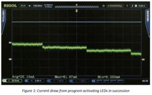
After establishing the best measurement technique for your system, I prefer to begin with a static measurement to establish baseline performance. Typically, I would use a standard example program. In this case, we will view the current draw from a simple program that toggles several LEDs. In this mode, we measure a baseline of about 5 mA. As shown in figure 1, activating each LED also requires 10-12 mA of current on this baseline.
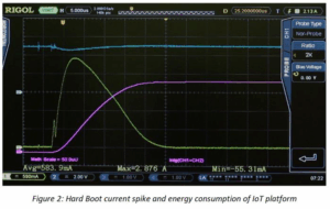
Second, establish a start-up or bootup power requirement for the system. Here, we conducted a test from a hard boot. In addition to power we are also monitoring the energy usage using the integration of voltage * current over time as an approximation. Refer to Figure 2. Understanding the start-up power requirements from different boot states is critical to optimizing the design for sleep or shutdown power mode usage.
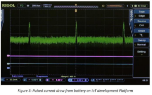
Not all of the peripherals utilize power in a DC fashion like LEDs. Test other peripherals you are using to see how they pull power from the battery. A simple test of the SPI bus demonstrates power being drawn in a pulsed fashion. Analysing the amplitude, width, and repetition rate of these current pulses (shown in Figure 3) enables us to understand the power usage.
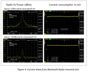
We can use a similar method to test the actual output power of the Bluetooth radio as well as the battery power used during the transmission. This is important once the complete RF antenna layout is completed since power shortages here could result from reflections or mismatch in the RF path. In the test, we leave the Bluetooth Low Energy radio in a constant power transmit to easily monitor the power consumption. In a real use case, the transmit function is never constant, but the power values here are a guide to optimization in on time and power for the radio use cases. In the results below, a transmit power of 0 dBm resulted in 83 mA of power usage while a transmit power of -40 dBm resulted in 67 mA of current. Even in an off state, the radio example uses significant power to prep the radio and peripherals. These baseline values help us to determine the radio power and transmit cycles that may fit into our customer use cases. RF and DC power are shown for these 2 cases in Figure 4.
Once we have determined typical power levels by state and peripheral usage, the next step is to verify that there are no other effects contributing to power usage when in a more dynamic mode of switching operational states. We can test our code examples using a function to both measure instantaneous power and energy over time. With this approach, we can now determine the energy usage of an approach over time and see how different sleep algorithms generally affect battery life. With this level of information, code optimization in response to customer needs becomes much simpler.
In order to complete the IoT design and get a product to market quickly and cost effectively, our information on power usage in different setups and modes is an invaluable tool. The completed tests have enabled us to gather information about static state power usage for our platform and our required peripherals. We also have details on sleep states and boot power from which we can make informed decisions about trade-offs between battery size and use times in our customer use models. With a basic understanding of how power is consumed in our system we can use this as a guideline for incremental improvements throughout our design cycle. For instance, we better understand the advantage of waiting to service the peripherals vs. putting the whole system into sleep mode for a short period. These decisions can then be validated and refined as your application and use cases become clear.
Conclusions and Key Learnings
When working in the fast-changing atmosphere of IoT design and development, reliable test methodologies become increasingly important. As engineers integrate the newest sensors and platforms on the fly to reach highly competitive markets as fast as possible, understanding core customer requirements and trade-offs and how those can be evaluated and compared throughout the development is an important step toward improving the strategic design process.
Whether the challenges of an application are more form or function, issues related to battery life and power usage are fundamental elements of design in the IoT ecosystem that play a significant role in market success. Establishing these principles early in the process and testing them iteratively is one of the best ways to limit budget and schedule risks in the latter stages of the design. Modern, easy to use test equipment that is more affordable than ever can be utilized to develop the limits and baselines that will guide an engineering team through a successful product development.
Products Mentioned In This Article:
- Digital Multimeters please see HERE


